To sign up for our daily email newsletter, CLICK HERE
Before initializing any large-scale design or assembly, teams must create a detailed technical drawing. These drawings are coordinate engineering layouts systematically and with precision. Whether it’s a building, a car gear, a floor joist bracket, or landscape and 3D model mapping, each project makes use of specific types of drawing. In addition, accurate technical drawings bring into harmony all the parties involved in the project, guaranteeing that each participant works with exact dimensions and details.
Why Technical Drawings Matter in Engineering?

Engineering drawing formats vary significantly across fields, including architectural design, HVAC systems, doorknob manufacturing, and watch polishing. Engineering Drawings were used even before the application of computer-aided manufacturing. Although computer technology allows some designs to be built without drawings, many important manufacturing projects still require precision drawings. The need comes from the fact that these drawings confirm CAD designs, they act as a guarantee that manufacturers are creating parts to exact specifications and act as a guide in inspecting the finished project.
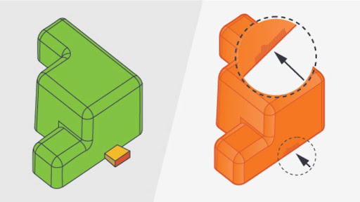
Even more, drawings contain scale, and critical elements for manufacturing including tolerances, surface finishes, material requirements, and thread information that may be tolerated in the CAD files. Apart from the technicality, drawings are legal and work as a contract between the customer and the manufacturer so no one can change the specifications of the product.
Last but not least, technical drawings are essential for deciding part geometry, dimensions, and cost approximation. They are still the only unchallengeable medium of communicating engineering instructions that leave no room for ambiguity and reduce risks in the course of a project.
Set Standards For Technical Drawings
The proposed standards ensure that technical drawings are clear and easy to understand. By following these standards, team members from different cultural backgrounds can interpret the drawings accurately.
ISO publication provides certain guidelines such as ISO 128 and for engineering drawings ISO 8015. However, the ASME also set its standards known as ASME Y14.5 and Y14.5M, which provide some rules for producing highly accurate engineering drawings.
ISO 128 provides basic standard requirements for 2D and 3D drawings. These are used in various areas of mechanical engineering, construction, architecture, and shipbuilding, for manual and digital drawing.
Technical Drawing Views and Key Features

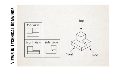
Views Showcase In Technical Drawings
Usually, a technical engineering drawing presents a complete view of an engineered product, to enable manufacturers to comprehend the engineer’s design from various angles. CNC machining or sheet metal drawings typically contain these essential views and elements:
- Isometric Views: Isometric views indicate the object as rotated 45 degrees on the vertical axis and 35.264 degrees on the horizontal axis. Such a view gives a three-dimensional one and depth hence you can get an actual impression of the object’s shape.
- Orthographic Views: Orthographic views are the projected views as seen from the front, right, left, top, bottom, or back of the object – known as multiview projection. Usually, it is enough to have two or three orthographic views for sharing the information.
- Auxiliary Views: Auxiliary views indicate additional 2D views apart from the six basic views. These are used where more perspectives are needed.
- Section Views: Section views are the views that show the object in a cut plane, which helps to show the inside part of the object. Such views are most often associated with an orthographic view.
- Detail Views: Detail views are utilized to capture specific, intricate aspects within an orthographic view to clear up those parts.
- Title Block: The title block is usually located at the bottom right of the page and contains information such as the part name, company, part and drawing number, material, finish, color, scale, and standards.
- Notes List: Extra remarks or flag notes can be observed along the drawing edges, which contain comments or suggestions for the end user.
How to Quickly Prepare a Technical Drawing?
CAD software simplifies creating technical drawings without needing a drafter. You can simply employ tools such as SolidWorks and choose “Make Drawing from Part/Assembly”. It allows to pre-inspect and simulate assembly and part functionality.
Drawing a picture from scratch; Another way to create a representation is by using CAD drawing software to build it from scratch. The following method is similar to manual technical drawing drafting, but technology helps reduce mistakes. However, it doesn’t allow for digital assembly or simulation.
Elements to Include in a Sheet Metal Technical Drawing
When preparing a technical drawing for sheet metal fabrication, the following features should be considered:
Material Gauge:
The physical property of sheet metal defines the material thickness, it affects the forming and cutting of the material. Moreover, it plays an important role in deciding the strength and material weight.
Grain Direction:
The direction of the grain determines how the material bends. Bending along the grain is easier than bending across the grain because the latter poses a high risk of cracking.
Torque Requirements:
State the torque values that should be used when assembling using screws or bolts. Different material thicknesses can handle varying levels of torque, which is crucial for assembly.
Weld Locations:
Point the welds and sizes. Perfectly visible features allow adequate assembly and alignment during the welding in the construction process.
Feature Dimensions:
Take measurements for bends, countersinks, and holes to exact levels. Dimensional correctness avoids fabrication mistakes and guarantees the part’s performance as intended.
Features To Include For CNC Machining Technical Drawings

Important Features To Include In Technical Drawings
Technical drawings required for CNC milling 2d drawings have to comprise certain information. These include tolerance that may vary within the area of interest depending on the required machining process, callout for holes such as countersink, and standard thread size instead of millimeters dimensions.
What to Include in an Injection Molding Technical Drawing?

Injection Molding Drawings
For injection molding, the following points are critical to include:
- Draft Angles: Determine the number of degrees of draft necessary for easy part removal from the mold. If a certain area cannot have the standard draft then it must be indicated on the drawing.
- Gate & Pin Locations: It’s necessary to determine the permitted locations for gate and ejector pins. This assists in controlling the flow of material and reducing the number of flaws that may happen during molding.
- Parting Line Location: Learn where the parting line is on the drawing to ensure you do not have problems with mold design. Particularly, it helps reduce defects and guarantees that the molded part interconnects perfectly.
What Should Be Put on a Die Casting Technical Drawing?
For die-casting, make sure to include the following features:
- Draft Angles: Set the correct draft angles through which the part can easily taken out from the mold.
- Gate & Parting Line Locations: Identify the limitations for gate and parting line placements to ensure optimum mold function. High-quality molding is crucial to avoid air inclusions.
- Wall Thickness: The minimum wall thickness should be provided while designing the particular piece to give it the appropriate strength and sturdiness. Hence, thin walls may pose an issue to the structural integrity.
What to Focus on When Designing Extrusion Drawing?
For extrusion technical drawings, the following features are important:
- Stock Size: The dimensions of a final product determine the size of the metal stock usually required indicating the stock size.
- Grain Direction: You can align the material’s grain direction to optimize strength for specific applications. Especially, important for materials like aluminum and stainless steel or construction use materials.
- Exposed Surfaces: Identify areas that need additional treatment to bring it to a finish. These areas may need special attention during manufacturing to fulfill aesthetic or performance requirements.
- Hole Callouts: Mark the size and position of any holes. Hole callouts are important to avoid any mistakes made during the manufacturing process and so the part works as intended.
Fields and Spheres of Technical Drawing
Technical drawings are employed in various sectors of the economy for precise definitions of design and production. Here are some of the key applications:
Aerospace Engineering: In aerospace, technical drawings are used to design parts and systems of an aircraft. They also ensure that all the components abide by the various standards of safety and performance.
Automotive Design and Manufacturing: Schematics are used in vehicle design and engineering from the early stage of the development process to the manufacturing stage. They can be used extensively in prototyping, tooling, and assembly processes.
Electronics and Electrical Engineering: Engineering drawings are very helpful in circuit and control system design. They help engineers to develop new and efficient electronic products.
Construction and Architecture: In construction technical drawings are applicable in the planning and design of structures. They contain specifics on structural mechanics and electric systems.
FAQ’s
Q1. What is an orthographic view in technical drawing?
An orthographic view is a view of an object in a two-dimensional plane where an object is drawn in different views as front, top, or side views. It helps show the object’s true shape and size.
Q2. Why are tolerances critical in technical drawings?
Tolerances are the permissible limits of dimension variation that affect the functionality and quality of the product during production.
Q3. What are section views used for in technical drawings?
Plans of sections demonstrate the internal details of the object by making a line across the object. They are necessary to show specific internal shapes that cannot be observed by external observation.
Q4.How are weld locations indicated on a technical drawing?
On technical drawings, the weld locations are indicated by certain symbols that describe the type and weld size. These details make it possible to fabricate and assemble appropriately during manufacturing.
Q5. What role do dimensions play in a technical drawing?
Correct dimensions define how close/far apart two features on a part can be or how large a feature has to be at a certain location. In addition, it tells about the part fit, and workability.